


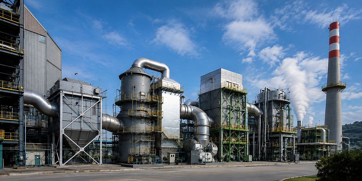
Flue gas from industrial boilers, sintering plants, pelletizing lines, coke ovens and other industrial furnaces rarely presents a single-pollutant problem.
SO₂, NOx and particulate matter may all be present, while flue gas temperature changes as the stream passes through particulate control, desulfurization and heat-recovery equipment.
For these applications, the engineering question is not simply which FGD unit to install or which DeNOx catalyst to select.
How should SO₂ removal and NOx reduction be arranged? Can the two catalytic stages operate within a continuous temperature profile? Is reheating necessary? And can useful heat still be recovered after pollutant control?
DAQI Technology combines its catalytic flue gas desulfurization technology with its ultra-low-temperature SCR technology in a two-stage treatment concept:
Particulate removal → Catalytic SO₂ removal → Ultra-low-temperature SCR → Heat recovery → Stack
“Integrated SO₂ and NOx control” does not mean that both pollutants are removed by a single catalyst in one reactor.
The process uses two separate catalytic stages. Integration takes place at the system level through process sequencing, flue gas conditioning and temperature matching.
Why Temperature Is Critical in Industrial SO₂ and NOx Control
Selective Catalytic Reduction, or SCR, is a well-established technology for post-combustion NOx control.
The U.S. Environmental Protection Agency describes SCR as a process in which a reducing agent and catalyst are used to chemically reduce NOx, with applications including industrial boilers, process heaters and other stationary sources. [1]
For many industrial applications, however, the main challenge is not the basic SCR chemistry. It is the required operating temperature.
Flue gas from coking, steel sintering, pelletizing and other non-power applications often reaches the downstream treatment system at substantially lower temperatures than those typically associated with conventional high-temperature SCR.
Research on low-temperature SCR also shows that these industrial gas streams may contain SO₂, moisture, particulate matter and other components that influence catalyst activity and long-term stability. [2]
If a gas stream has already been cooled during particulate control, desulfurization or heat recovery, reheating the entire flue gas volume solely to reach a conventional SCR temperature window adds energy consumption and operating cost.
In practical terms, the process can become:
Cooling → Pollutant treatment → Reheating → SCR → Cooling again
For continuously operated industrial plants, repeated temperature adjustment becomes a real operating-cost issue.
Ultra-low-temperature SCR is intended to reduce this temperature mismatch.
90–180°C: Extending SCR into the Ultra-Low-Temperature Range
Following continued optimization of catalyst formulation, active components and process conditions, DAQI Technology’s current ultra-low-temperature SCR technology can cover an application window of approximately 90–180°C, depending on actual flue gas conditions.
The significance of this wider temperature window is not simply a lower headline operating temperature.
More importantly, some industrial flue gas streams that have already cooled after particulate removal, desulfurization or heat recovery can be treated without first reheating the entire gas stream to the much higher temperatures commonly required by conventional SCR configurations.
For suitable applications, the treatment sequence can therefore become:
Existing flue gas temperature → Catalytic FGD → Ultra-low-temperature SCR → Heat recovery
rather than repeatedly heating and cooling the gas between pollution-control stages.
It is important, however, to distinguish between an application temperature range and a guaranteed operating point.
A lower boundary of approximately 90°C does not mean that every flue gas stream at 90°C can use the same catalyst, space velocity and operating parameters.
Actual performance must also be evaluated against NOx concentration, SO₂/SO₃, moisture, O₂, particulate loading, space velocity, NH₃/NOx ratio and the required outlet emission level.
How Does the Combined Catalytic FGD and Ultra-Low-Temperature SCR Process Work?
The treatment train contains two principal catalytic stages.
Stage 1: Catalytic SO₂ Removal
After upstream particulate control, the flue gas first enters the catalytic desulfurization reactor.
DAQI Technology’s catalytic FGD process uses carbon-based catalytic materials rather than relying on physical adsorption alone.
The porous carbon structure provides a large internal reaction interface, while surface active sites help concentrate SO₂, O₂ and H₂O and promote further oxidation and conversion of SO₂.
The process can be summarized as:
SO₂ adsorption → Catalytic oxidation → H₂SO₄ formation → Water-washing regeneration
DAQI Technology’s current catalytic desulfurization technology can be applied over approximately 40–180°C, depending on the catalyst system, flue gas composition and process design.
As sulfuric acid accumulates within the catalyst pores, it can be removed through water washing. Occupied active sites are reopened and the catalyst can return to service.
The desulfurization stage therefore performs two functions in the integrated process:
- controlling SO₂ emissions;
- reducing the sulfur load entering the downstream ultra-low-temperature SCR reactor.
Why Is Desulfurization Installed Before Ultra-Low-Temperature SCR?
This process sequence is important.
NH₃-SCR requires ammonia, or ammonia generated from a urea system, as the reducing agent.
When SO₂/SO₃, NH₃ and moisture coexist under low-temperature conditions, ammonium bisulfate, NH₄HSO₄ (ABS), and ammonium sulfate deposits may form.
Published reviews of industrial SCR catalyst deactivation identify sulfur-related ammonium salt deposition as an important issue in low-temperature operation. [3]
Low-temperature SCR research also describes how SO₂ may be oxidized to SO₃ and subsequently react with NH₃ and H₂O to produce ammonium sulfate species that can cover the catalyst surface, block pores and affect catalytic activity. [2]
For this reason:
Upstream desulfurization is not simply a matter of equipment order. It also helps reduce the sulfur burden placed on the downstream SCR catalyst.
This does not eliminate every sulfur-related risk.
SO₂/SO₃ concentration, moisture, ammonia slip, gas temperature, space velocity and catalyst sulfur tolerance still need to be evaluated for each application.
Stage 2: Ultra-Low-Temperature SCR for NOx Reduction
After SO₂ removal, the flue gas enters the ultra-low-temperature SCR reactor.
SCR stands for Selective Catalytic Reduction.
In the presence of a catalyst, NH₃ reacts selectively with NO and NO₂, producing mainly nitrogen and water.
Representative reactions include:
4NH₃ + 4NO + O₂ → 4N₂ + 6H₂O
4NH₃ + 2NO₂ + O₂ → 3N₂ + 6H₂O
The fundamental SCR chemistry does not change at lower temperature.
What changes is the catalyst’s ability to maintain useful NOx conversion activity, sulfur and moisture tolerance, and stable reaction performance over a substantially lower temperature range.
Through continued optimization of active components, support structure, pore structure and surface reaction properties, DAQI Technology’s current ultra-low-temperature SCR platform can cover approximately 90–180°C.
This provides an alternative for industrial gas streams where conventional SCR would otherwise require substantial reheating.
A Typical Integrated SO₂ and NOx Treatment Sequence
The following temperatures illustrate one representative process configuration.
These values describe a typical process arrangement and should not be interpreted as the complete operating range of DAQI Technology’s catalytic technologies.
| Process Stage | Representative Temperature | Main Function |
|---|---|---|
| Incoming flue gas | 135–180°C | Flue gas from boilers, sintering or related processes |
| Dry particulate removal | 125–160°C | Reduce particulate loading before catalytic treatment |
| Catalytic desulfurization | Approx. 120–140°C | SO₂ removal and catalytic conversion |
| Ultra-low-temperature SCR | Approx. 120–140°C | NOx reduction; current DAQI Technology SCR capability covers approximately 90–180°C |
| Low-temperature heat recovery | Project-specific | Recover remaining sensible heat |
| Stack | Approx. 50°C in the illustrated case | Final discharge according to system design |
Technical note: The 120–140°C values in the process diagram represent one typical operating condition. They do not define the full operating window of the technology. DAQI Technology’s current ultra-low-temperature SCR technology can cover approximately 90–180°C, subject to actual flue gas conditions.
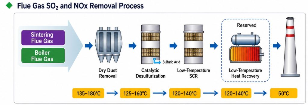
The important point in the process diagram is not the specific value of 120–140°C.
It is the temperature continuity between the two catalytic stages.
If the gas leaving the catalytic FGD stage remains within the effective operating window of the selected ultra-low-temperature SCR catalyst, NOx reduction can follow without substantially reheating the entire flue gas stream.
Why Use a Desulfurization-First, SCR-Second Configuration?
Lower Sulfur Loading on the SCR Catalyst
Low-temperature SCR is particularly sensitive to interactions between sulfur compounds, moisture and NH₃.
Reducing SO₂ upstream lowers the sulfur load placed on the downstream catalyst and can reduce the risk associated with sulfur-containing ammonium deposits.
This is particularly important for complex industrial flue gas such as coking and sintering exhaust.
Better Temperature Continuity
If one pollution-control stage operates near 100–150°C but the next requires the entire gas stream to be reheated above 300°C, the treatment train contains an obvious thermal penalty.
Combining 40–180°C catalytic SO₂ removal with a 90–180°C ultra-low-temperature SCR platform is intended to narrow this temperature gap.
For suitable applications, the sequence becomes:
Particulate control → Catalytic FGD → Ultra-low-temperature SCR → Heat recovery
The energy benefit does not come from generating additional heat.
It comes from reducing the reheating load that might otherwise be required.
Heat Recovery Can Be Considered as Part of the Same System
Where useful sensible heat remains after SO₂ and NOx control, downstream low-temperature heat recovery can be evaluated.
The overall engineering objective therefore becomes:
Pollutant control + Thermal integration + Operating energy
rather than simply maximizing the removal efficiency of one individual unit.
Key Features of the Integrated Process
90–180°C Ultra-Low-Temperature SCR Window
The expanded low-temperature application window allows selected industrial flue gas streams to be treated at temperatures well below those typically associated with conventional SCR systems.
For suitable operating conditions, this can reduce the need for substantial flue gas reheating.
Two Catalytic Stages Rather Than One Multi-Pollutant Catalyst
Catalytic FGD controls SO₂, while ultra-low-temperature SCR controls NOx.
Each reactor performs a different function. The two stages work together through temperature matching and flue gas conditioning.
Regenerable Catalytic Desulfurization Material
Sulfuric acid accumulated within the carbon-based desulfurization catalyst can be removed through water washing.
This reopens occupied active sites and allows the catalyst to return to service.
The operating concept can be summarized as:
Adsorption → Catalytic conversion → Sulfuric acid formation → Regeneration → Reuse
Reduced Reheating Demand
Where actual gas conditions fall within the effective ultra-low-temperature SCR window, substantial reheating may be reduced or, in suitable cases, avoided.
This should not be interpreted as meaning that every project requires no supplemental heat.
Compatibility with Low-Temperature Heat Recovery
After SO₂ and NOx control, remaining sensible heat can be evaluated for downstream recovery according to gas temperature, acid dew point, equipment materials and project economics.
Project-Specific Engineering
There is no universal industrial flue gas composition.
Catalyst formulation, catalyst volume, reactor dimensions, space velocity, NH₃ injection, pressure drop and operating conditions need to be selected from actual process data.
Typical Industrial Applications
Iron and Steel Sintering and Pelletizing
Sintering and pelletizing flue gas can contain particulate matter, SO₂ and NOx simultaneously.
This makes these processes suitable candidates for system-level multi-pollutant treatment rather than isolated pollutant-control decisions.
China’s GB 28662-2012, Emission Standard of Air Pollutants for Sintering and Pelletizing of Iron and Steel Industry, establishes relevant emission-control requirements for these facilities. [4]
For actual projects, existing particulate-control equipment, gas temperature, SO₂ concentration and NOx concentration should be considered together.
Coke Ovens and Coking Plants
Coking flue gas commonly presents relatively low temperatures, complex compositions and fluctuating operating conditions.
These characteristics make low- and ultra-low-temperature SCR particularly relevant to this sector.
China’s updated GB 16171.1-2024, Emission Standard of Air Pollutants for Coking Chemical Industry applies to new enterprises from April 1, 2025, while existing enterprises are required to comply from January 1, 2027. [5]
Industrial Boilers
Industrial boilers are another common source where SO₂ and NOx control may need to be considered together.
China’s GB 13271-2014, Emission Standard of Air Pollutants for Boiler, establishes relevant air-pollutant emission requirements for boiler installations. [6]
Where boiler flue gas temperature is already relatively low, ultra-low-temperature SCR can be evaluated against conventional reheated SCR from both a process and lifecycle-cost perspective.
Other Industrial Furnaces and Process Gas
Selected metallurgical, building-material, chemical and combustion processes may also be suitable for integrated SO₂ and NOx treatment.
Industry name alone, however, is not enough to select the technology.
Actual flue gas data should be evaluated first.
Can SCR Really Operate at 90°C?
DAQI Technology’s current ultra-low-temperature SCR technology can cover approximately 90–180°C, but this does not mean that every flue gas stream at 90°C can use identical catalyst and operating parameters.
Temperature is only one part of the engineering assessment.
A preliminary project evaluation should normally include:
- Flue gas flow rate, Nm³/h
- Normal, minimum and maximum temperature
- Inlet SO₂ concentration
- SO₃ concentration, if available
- Inlet NOx concentration
- Required outlet SO₂ and NOx levels
- O₂ concentration
- Moisture
- Particulate concentration and composition
- Other potential catalyst poisons
- Gas pressure and allowable pressure drop
- Annual operating hours and load variation
- Existing particulate, FGD, DeNOx and heat-recovery equipment
- Available installation space
These parameters determine catalyst formulation, catalyst volume, space velocity, reactor dimensions, ammonia injection and long-term operating stability.
The real engineering match is not a single minimum-temperature figure. It is:
Catalyst × Flue gas conditions × Reactor design × Process control
From Individual Pollutant Removal to Integrated Flue Gas Treatment
DAQI Technology develops carbon-based catalytic materials, catalytic flue gas desulfurization technology and ultra-low-temperature SCR technology for industrial flue gas treatment.
Individually:
- Catalytic desulfurization addresses low-temperature SO₂ adsorption, catalytic conversion, catalyst regeneration and sulfur recovery.
- Ultra-low-temperature SCR addresses catalytic NOx reduction over an application window of approximately 90–180°C.
When the two technologies are integrated, the engineering objective extends beyond meeting two separate emission limits.
The complete system can instead be considered as:
Particulate removal → Catalytic FGD → Ultra-low-temperature SCR → Heat recovery → Stack
This system-level approach is the main difference between an integrated SO₂/NOx treatment process and a standalone FGD or SCR unit.
For project evaluation, catalyst selection, reactor configuration and operating parameters should be based on flue gas flow, temperature, SO₂, SO₃, NOx, moisture, oxygen, particulate loading and required outlet concentrations.
Frequently Asked Questions
Are SO₂ and NOx removed in the same reactor?
No.
The process uses two separate catalytic stages. Catalytic desulfurization treats SO₂ first, followed by NOx reduction in an ultra-low-temperature SCR reactor.
What is the operating temperature of DAQI Technology’s ultra-low-temperature SCR technology?
The current technology can cover approximately 90–180°C, depending on actual flue gas conditions.
Final operating conditions must also consider NOx, SO₂/SO₃, moisture, O₂, particulate loading, space velocity and the required outlet emission level.
Why is desulfurization installed before SCR?
One important reason is to reduce the SO₂/SO₃ load entering the SCR reactor.
Under low-temperature NH₃-SCR conditions, sulfur-related ammonium salt deposition can affect catalyst pores and active sites.
Can a 90°C flue gas stream always be treated directly by SCR?
No.
Approximately 90°C represents the lower boundary of the current application range under suitable conditions, not a universal guaranteed operating point.
Complete flue gas data and project-specific catalyst selection are still required.
Does ultra-low-temperature SCR eliminate reheating?
Not in every application.
Where actual flue gas conditions are already within the catalyst’s effective operating window, substantial reheating can be reduced or sometimes avoided.
Supplemental temperature control may still be required in other projects.
Which industries can evaluate this process?
Potential applications include industrial boilers, coking plants, iron and steel sintering, pelletizing, industrial furnaces and selected metallurgical, building-material and chemical processes.
Final suitability depends on actual flue gas data and emission requirements.
What data is required for a preliminary technical evaluation?
The main starting parameters are:
Flue gas flow + Minimum and normal temperature + SO₂ + SO₃ + NOx + Moisture + O₂ + Particulate concentration + Required outlet levels + Existing flue gas treatment configuration
References
- U.S. Environmental Protection Agency. Air Pollution Control Technology Fact Sheet — Selective Catalytic Reduction (SCR).
- Zhu H., Song L., Li K., Wu R., Qiu W., He H. Low-Temperature SCR Catalyst Development and Industrial Applications in China. Catalysts, 2022, 12(3), 341.
- Szymaszek A., Samojeden B., Motak M. The Deactivation of Industrial SCR Catalysts—A Short Review. Energies, 2020, 13(15), 3870.
- Ministry of Ecology and Environment of China. Emission Standard of Air Pollutants for Sintering and Pelletizing of Iron and Steel Industry — GB 28662-2012.
- Ministry of Ecology and Environment of China. Emission Standard of Air Pollutants for Coking Chemical Industry — GB 16171.1-2024. See also the official MEE announcement.
- Ministry of Ecology and Environment of China. Emission Standard of Air Pollutants for Boiler — GB 13271-2014.
Technical note: In this article, approximately 40–180°C refers to the application window of DAQI Technology’s catalytic flue gas desulfurization technology, while approximately 90–180°C refers to the application window of its ultra-low-temperature SCR technology. Actual project performance depends on flue gas composition, pollutant concentrations, moisture, particulate loading, space velocity, catalyst formulation and reactor design. The 120–140°C temperatures shown in the process diagram represent one typical process configuration rather than the full technology range.